A Miniature Motor is small in size, yet its engineering can be remarkably demanding. It converts electrical energy into controlled mechanical movement inside devices such as camera lenses, medical pumps, robotic joints, toys, and precision instruments. Austin Hughes, a respected author on electric motor systems, describes the basic principle clearly: “An electric motor is a device that converts electrical energy into mechanical energy.” That simple sentence explains the foundation, but not the design challenges hidden inside a motor only a few millimeters wide.
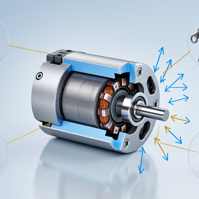
Inside the housing, current flows through coils and creates a magnetic field. The field interacts with permanent magnets, producing torque on the rotor. A commutator and brushes may switch the current mechanically, while brushless designs use electronic control. Bearings support the rotating shaft. Tiny parts must still manage heat, vibration, noise, friction, and wear. They must also deliver predictable speed and torque.
Size changes everything.
A designer may gain compactness but lose cooling capacity. Higher speed can improve responsiveness, yet it may increase noise and shorten service life. Real-world testing matters because calculations rarely capture every vibration or assembly error. Even experienced engineers can overlook a small imbalance. That is an uncomfortable limitation, but it deserves attention.
This guide explains what a Miniature Motor is, how its electromagnetic action produces rotation, and why different motor types suit different applications. It also examines efficiency, control methods, materials, and practical selection criteria. The goal is not to make miniature motors seem mysterious. It is to show the precise decisions behind their quiet, powerful movement.
What Is a Miniature Motor and How Does It Work?
A miniature motor is a compact electromechanical device that converts electrical energy into controlled rotation. In many practical applications, it operates from 3–12 V and measures less than 100 mm across its main body or complete assembly. This range is useful for small pumps, camera mechanisms, handheld instruments, toys, and lightweight automation. The boundary is not absolute. A motor with a 70 mm body may become much larger after adding a gearbox, shaft, or mounting bracket.
Inside a brushed DC miniature motor, current enters through the terminals and reaches the windings on the rotor. Magnetic forces then push against permanent magnets in the stator, creating rotation. A commutator and brushes repeatedly switch the current direction, keeping the rotor moving. Brushless and stepper designs use electronic control instead. A gearbox can reduce speed while increasing torque. It often makes the motor more useful, but also adds noise, friction, and mechanical wear.
A practical selection check starts with voltage, no-load speed, rated torque, and stall current. Never judge performance by voltage alone. A 6 V motor may draw only 80 mA while spinning freely, then demand several times more under load. That difference can overheat a small driver or shorten the motor’s service life. During bench testing, measure current after the motor reaches its working load, and allow for heat buildup in enclosed spaces. Small does not mean simple. The 100 mm guideline is helpful, but real performance depends on winding design, bearings, cooling, and the attached mechanism.
| Motor Type | Typical Supply Voltage | Typical Motor Size | Typical Speed or Output | Typical Torque Characteristics | How It Works | Common Applications |
|---|---|---|---|---|---|---|
| Brushed DC Motor | 3–12 V DC | Approximately 10–36 mm diameter; often 20–60 mm long | Approximately 3,000–20,000 rpm without a gearbox | Low continuous torque; torque increases as current rises and speed falls | Current flows through brushes and a commutator into the armature windings. The magnetic interaction between the armature and permanent magnets produces continuous rotation. | Toys, small pumps, fans, optical mechanisms, handheld devices, and compact actuators |
| Coreless DC Motor | 3–12 V DC | Approximately 6–24 mm diameter; commonly below 50 mm long | Approximately 5,000–30,000 rpm without a gearbox | Very low rotor inertia and fast response; best suited to short acceleration and deceleration cycles | The rotor uses a lightweight hollow winding structure rather than a conventional iron core. This reduces inertia while the commutator and brushes electronically switch current through the rotor coils. | Camera lens mechanisms, miniature valves, medical instruments, precision positioning, and portable equipment |
| Brushless DC Motor | 3–12 V DC | Approximately 15–40 mm diameter; commonly below 70 mm long | Approximately 2,000–30,000 rpm, depending on winding and control | Good efficiency and longer operating life; usable torque depends strongly on the controller and cooling conditions | An electronic controller switches current through stationary stator windings in sequence. Permanent magnets on the rotor follow the rotating magnetic field, eliminating mechanical brushes. | Cooling fans, miniature pumps, drones, laboratory equipment, hard-drive mechanisms, and precision instruments |
| Miniature Gearmotor | 3–12 V DC | Approximately 12–37 mm diameter; commonly below 80 mm long | Approximately 10–1,000 rpm at the gearbox output | Higher output torque and lower speed than the motor alone; gearbox efficiency typically reduces available output power | A DC or brushless motor drives a reduction gear train. The gears trade rotational speed for increased output torque and make low-speed movement easier to control. | Robotic joints, small wheels, locks, dispensing mechanisms, compact conveyors, and adjustable mechanisms |
| Miniature Stepper Motor | 5–12 V DC, usually through a current-controlled driver | Approximately 20–42 mm frame size; commonly below 60 mm long | Typically 100–2,000 steps per second, with torque decreasing as speed increases | Provides holding torque when energized; positioning accuracy depends on step angle, load, driver, and mechanical design | The driver energizes multiple stator phases in a defined sequence. The rotor aligns with each changing magnetic field, producing discrete angular steps without requiring a position sensor for basic operation. | Small printers, camera platforms, laboratory stages, valves, gauges, and low-speed positioning systems |
| Miniature Vibration Motor | 3–5 V DC | Approximately 8–12 mm diameter; commonly below 25 mm long | Approximately 8,000–15,000 rpm | Produces vibration rather than controlled shaft torque; vibration strength depends on eccentric mass and speed | A small DC motor rotates an off-center mass. The imbalance generates centrifugal force, creating vibration that can be felt by the user or detected by a sensor. | Mobile alerts, wearable devices, handheld electronics, toys, and compact haptic interfaces |
| Miniature Linear Actuator Motor | 6–12 V DC | Typically 20–50 mm body diameter; overall length often below 100 mm | Approximately 1–20 mm/s linear travel, depending on gearing and lead screw | Higher force at lower travel speed; output force varies significantly with screw pitch and motor current | A rotating motor drives a lead screw or threaded mechanism. The screw converts rotary motion into controlled linear movement and can provide mechanical self-locking at suitable pitches. | Miniature vents, latches, optical assemblies, medical mechanisms, and compact positioning systems |
It is a compact device that converts electrical energy into controlled rotation. Typical systems use 3–12 V and measure under 100 mm. The boundary is not exact.
Current enters the windings on the rotor. Magnetic forces push against permanent magnets in the stator. Brushes and a commutator reverse current repeatedly, keeping the shaft moving. Small parts matter.
Current-carrying conductors experience force inside a magnetic field. The relationship is F = BIL sin θ. Opposing forces on coil sides create torque around the shaft. Air-gap changes can affect smoothness.
Back EMF is voltage generated by rotating coils. It opposes the supplied voltage and rises with speed. The relationship is E = keω. At startup, speed and back EMF are nearly zero.
A heavier load slows the shaft. Lower speed reduces back EMF, allowing more current to flow. More current usually creates more torque. Heat can build quickly.
A 6 V motor may draw 80 mA without a load. Under working load, current can become several times higher. Check rated torque, speed, startup current, and temperature too.
A gearbox reduces speed and increases available torque. It may help drive a small pump or mechanism. However, it also adds noise, friction, and wear. More torque is not free.
Measure voltage, current, speed, and temperature together. Test after the motor reaches its actual working load. Watch enclosed spaces, where heat escapes poorly. Sound alone is unreliable.
A Miniature Motor is a compact electric motor typically designed for systems operating at 3–12 volts and measuring less than 100 millimeters. Its main components include the stator, rotor, windings, magnets, bearings, and, in some designs, a commutator. When current flows through the windings, magnetic fields interact and create torque through the Lorentz force, causing the rotor to turn. As the rotor spins, it also generates back electromotive force, which limits current and helps determine the motor’s operating speed and efficiency.
Different miniature motor types suit different applications. Brushed DC motors provide simple control and high RPM, while brushless DC motors offer longer life, lower maintenance, and quieter operation. Stepper motors deliver precise positioning, although their speed and efficiency may be lower. Gearmotors combine a motor with gears to increase output torque and reduce speed. Performance can be evaluated through IEC 60034 ratings, efficiency, heat generation, noise, torque, speed, control requirements, and expected service life.

 DyneticPro Motor