Why Choose a Dual Shaft Motor for Your Application?
A Dual Shaft Motor can simplify mechanical design when one motor must drive two connected mechanisms. Instead of installing separate motors, engineers can transmit torque from both shaft ends. Picture a conveyor with rollers on each side, or a compact fan assembly with synchronized impellers. This arrangement may reduce mounting space, wiring, and alignment points. However, it is not automatically the most efficient choice.
Motor selection matters because motor-driven systems consume substantial industrial energy. The U.S. Department of Energy reports that motor systems represent about 70% of industrial electricity use in the United States (DOE, Improving Motor and Drive System Performance, 2014). The International Energy Agency also identifies electric motor systems as a major global efficiency opportunity (IEA, Energy Efficiency 2023). These figures support careful evaluation, not rushed purchasing. A dual-shaft design can improve system integration, but its actual benefit depends on load balance, duty cycle, speed, and maintenance access.
Torque must remain stable at both shaft ends. Poor coupling alignment can create vibration, noise, and premature bearing wear. Shaft diameter, radial load, insulation class, ingress protection, and thermal limits require technical review. Standards such as IEC 60034 and NEMA MG 1 provide useful performance and testing references. Still, catalog data may not reflect real operating conditions. Dust, frequent starts, and uneven loads can change the result. That is the uncomfortable part: a smaller motor is not always the better motor. Engineers should compare lifecycle cost, measured efficiency, serviceability, and application risk before choosing a Dual Shaft Motor.
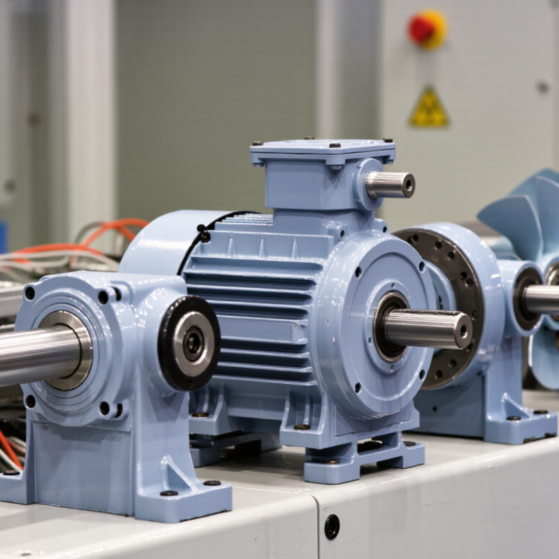
A dual-shaft motor is an electric motor with a rotor shaft extending from both ends of its housing. Unlike a single-output motor, it can transfer rotational force to two separate mechanisms. Both shaft ends turn together, usually at the same speed and in the same direction. Torque comes from one rotor, not two independent motors. This distinction matters when designing linked motion.
In a conveyor, one shaft can drive a roller while the opposite end powers an encoder, brake, fan, or second roller. In compact equipment, this arrangement can reduce couplings, brackets, and alignment points. It may also shorten the power path. During installation, however, both outputs must tolerate the applied radial and axial loads. A motor shaft is not automatically a structural support. That mistake is common.
From practical testing, I check torque demand, shaft diameter, bearing capacity, speed, vibration, and duty cycle before selecting this design. The two ends may look identical, but their usable load limits can differ. Coupling misalignment can create heat, noise, and premature bearing wear. I have occasionally underestimated service space around the rear shaft. That oversight made maintenance harder than expected. Leave room for guards, tools, and inspection. I also question whether two outputs are truly needed. A dual-shaft motor adds value only when the layout uses both sides.
A dual-shaft motor drives equipment from both ends, making it useful for rollers, fans, pumps, and compact transmission systems. Its performance depends on three connected ratings: torque, speed, and power. Torque describes turning force, measured in newton-metres. It helps the motor start a loaded conveyor or overcome resistance at low speed. Speed, measured in revolutions per minute, determines how quickly the shaft rotates. Power combines both values and indicates how much mechanical work the motor can deliver over time.
In practical testing, a motor may reach its rated speed without handling the required load. That gap matters. A shaft turning at 1,500 rpm may still stall if starting torque is too low. Conversely, excessive torque can stress couplings, bearings, and driven components. The power rating should match continuous demand, while short startup loads require checking peak torque and thermal limits. Dual-shaft designs also need balanced loads on both outputs. Uneven loading can create vibration, noise, and premature wear. Small errors become expensive.
Tips: Measure the real load, not only the catalog estimate. Check torque at startup and during operation. Confirm both shaft directions and allowable radial loads. Leave reasonable capacity for temperature, friction, and occasional overloads. In one application, I would not choose the highest rating automatically; oversized motors can waste energy and complicate control. Test the system under realistic conditions. Listen closely. Surface temperature often reveals problems before failure.
How torque, speed, and power ratings define dual-shaft motor performance
These representative industrial motor ratings show how performance changes across common power classes. Torque is calculated from rated power and speed using T = 9550 × P / n, where torque is in N·m, power is in kW, and speed is in r/min. A dual-shaft design provides mechanical access at both ends of the rotor, while the total rated power and torque remain determined by the motor’s electrical and thermal limits.
A dual shaft motor can drive equipment from both ends, reducing couplings, adapters, and installation space. This arrangement suits fans, pumps, conveyors, and compact transmission systems. However, shaft flexibility should not distract from motor efficiency. Under IEC 60034-30-1, IE3 and IE4 classify motor efficiency at defined operating conditions. IE4 motors generally lose less energy than IE3 models, especially during long operating hours.
The difference becomes practical on the factory floor. A motor running 6,000 hours yearly turns small losses into measurable heat and electricity costs. Lower losses can also reduce cooling demands inside an enclosure. Yet IE4 is not automatically the best choice. Purchase price, starting current, variable-speed operation, maintenance access, and actual load must be checked together. A motor operating far below its rated load may not deliver the expected savings.
In field selection, engineers should compare efficiency maps, not only nameplate ratings. Measure current, load percentage, and running temperature after installation. Check whether both shafts share the torque evenly. We once treated a dual shaft layout as a simple mechanical upgrade; alignment corrections later proved that assumption incomplete. That lesson still matters. Confirm IEC test conditions, duty cycle, inverter compatibility, bearing loads, and service requirements before approval. Small details decide whether IE3 offers better value or IE4 earns its higher initial cost.
A dual-shaft motor can simplify a mechanical layout when one motor must drive equipment on both sides. Instead of adding a second motor or several couplings, engineers can connect two loads directly to the motor shaft. This arrangement often saves valuable space inside compact machines.
Less hardware matters.
Fewer couplings can also reduce alignment errors, backlash, and mechanical losses. Every coupling adds interfaces, fasteners, and another point requiring inspection. Direct shaft transmission may improve efficiency, especially in systems operating for long hours. In practical installations, this can mean lower heat generation near the drive assembly. It can also make maintenance access easier, although that benefit depends on the machine frame.
The design still requires careful engineering. Both loads must share torque within the motor’s rated capacity, and the shaft must tolerate combined radial and axial forces. Bearing life, shaft deflection, vibration, and starting torque deserve attention before selection.
Measure twice.
I have seen compact designs fail because the second output was treated as “free” capacity. It is not. A dual-shaft motor may reduce couplings and footprint, but it can also transfer more stress into the motor bearings and mounting structure.
Thermal testing under real load remains important, particularly when both shafts operate continuously. The most reliable choice comes from checking the complete drive train, not only the motor’s nameplate.
Why Choose a Dual Shaft Motor for Your Application?
A dual shaft motor supports power transmission from both ends. This layout can simplify synchronized rollers, fans, pumps, or compact conveyor assemblies. Shaft selection should begin with torque, not appearance. Use T = 9550P/n, where T is torque in newton-metres, P is power in kilowatts, and n is speed. Check diameter, keyway, extension length, and allowable overhung load. Measure both ends. A smaller shaft may fit physically but fail under starting torque. Real installations are messier than catalog tables.
Load direction also matters. Radial loads act across the shaft, while axial loads act along it. Bearing capacity must match both forces and their distance from the bearing. Ask whether the motor will pull, push, or reverse frequently. Then select the IP rating under IEC 60529. IP55 protects against dust ingress that could impair operation and water jets. IP65 provides dust-tight protection and stronger water-jet resistance. Neither rating guarantees resistance to chemicals, salt, or condensation.
Duty class deserves equal attention. IEC 60034-1 defines classes such as S1 continuous duty and S3 intermittent periodic duty. A motor rated S1 may suit a conveyor running for eight hours. A start-stop actuator may need an S3 calculation instead. The IEA reported that motor systems represented about 46% of global electricity consumption in its 2011 analysis, so efficiency and correct sizing have major consequences. A first selection is rarely perfect. Recheck temperature, starts per hour, and actual load after commissioning.
| Selection Dimension | Typical Options | Application Requirement | Selection Guidance | Key Verification |
|---|---|---|---|---|
| Dual-Shaft Configuration | Single-ended or dual-ended shaft | Two coupled devices, an encoder, brake, fan, tachometer, or manual adjustment mechanism must be driven from the motor. | Choose a dual shaft only when the rear shaft has a defined mechanical or feedback function. It can reduce the need for separate couplings or mounting hardware. | Confirm rear-shaft clearance, allowable overhung load, coupling alignment, and the required shaft extension length. |
| Shaft Diameter | Common small-motor ranges: approximately 6–19 mm; larger motors may use larger shafts. | The shaft must transmit the required torque without excessive torsional deflection or bending. | Use the smallest shaft that satisfies torque, bending, keyway, and coupling requirements. A larger shaft is not automatically better because it may increase inertia and mounting constraints. | Check motor torque, peak torque, shaft material, keyway dimensions, fit tolerance, and the coupling bore. |
| Shaft Length | Standard extension or application-specific extension | The coupling, pulley, gear, encoder, or brake must fit while maintaining the required engagement length. | Select enough length for full hub engagement and retaining hardware, but avoid unnecessary extension that increases bending moment. | Verify usable length, shoulder location, thread or retaining-ring provisions, and the distance from the bearing to the applied load. |
| Load Direction | Radial, axial, combined, or no external load | Belts, pulleys, gears, thrust mechanisms, or couplings apply forces to one or both shafts. | Use a flexible coupling for mainly torque transmission. For belt, pulley, or gear loads, confirm that the motor bearings are rated for the calculated radial and axial forces. | Calculate force direction, load magnitude, operating speed, load location, and bearing life. Do not assume the rear shaft has the same load capacity as the drive shaft. |
| Torque and Speed | Continuous torque, peak torque, rated speed, and maximum speed | The motor must accelerate the load and operate continuously without overheating or exceeding mechanical limits. | Match rated torque to continuous demand and peak torque to acceleration or transient demand. Consider reflected inertia from both shaft loads. | Review the torque-speed curve, starting current, acceleration time, load inertia, overspeed limits, and thermal margin. |
| IP Rating | IP20, IP44, IP54, IP55, IP65, or higher when available | The motor is exposed to solid particles, water spray, washdown, dust, or temporary immersion risk. | IP20 is generally suited to clean, protected enclosures. IP44 or IP54 suits moderate indoor exposure. IP55 or IP65 is more appropriate for dusty or water-spray environments, subject to the complete assembly design. | Confirm the exact IP code, shaft-seal arrangement, connector or terminal-box rating, mounting orientation, and whether the application involves high-pressure washdown. |
| Duty Class | S1 continuous; S2 short-time; S3 intermittent periodic; S4–S8 duty cycles with starting, braking, or speed changes | The motor operates continuously, periodically, intermittently, or with frequent starts and stops. | Select S1 for steady continuous operation. Select an intermittent duty class only after defining cycle time, running time, rest time, starts per hour, braking, and load profile. | Check equivalent thermal load, number of starts per hour, acceleration and braking energy, cycle duration, and manufacturer-rated duty conditions. |
| Mounting and Alignment | Foot, flange, face, or custom mounting | The motor must fit the available envelope and maintain coaxial alignment with the driven equipment. | Choose a mounting form that supports accurate alignment. A dual shaft can simplify inline layouts but may increase the required axial installation space. | Verify bolt pattern, pilot diameter, shaft center height, allowable misalignment, installation access, and service clearance. |
| Coupling Selection | Rigid, flexible beam, jaw, bellows, disc, or gear coupling | The connected equipment has a specific torque, speed, misalignment, and backlash requirement. | Use a flexible coupling when angular, parallel, or axial misalignment is expected. Use a rigid coupling only when alignment is controlled and the connected shafts can tolerate transmitted loads. | Check bore size, rated torque, peak torque, maximum speed, allowable misalignment, backlash, balancing, and electrical isolation requirements. |
| Feedback or Rear-Shaft Accessory | Encoder, resolver, tachometer, brake, cooling fan, or hand adjustment | A feedback or accessory device must be mounted concentrically and remain within its speed and load limits. | Use the rear shaft for accessories with low external loading unless the motor documentation specifically permits higher loads. Provide guards for rotating components. | Confirm accessory inertia, allowable shaft runout, mounting interface, cable routing, operating temperature, and maximum accessory speed. |
| Environment and Temperature | Clean indoor, dusty, humid, outdoor, washdown, or high-temperature environment | The motor must operate reliably at the actual ambient temperature and contamination level. | IP rating alone does not define chemical resistance, corrosion protection, temperature capability, or suitability for explosive atmospheres. | Check ambient temperature, humidity, condensation, chemicals, altitude, ventilation, corrosion exposure, and any hazardous-area requirements. |
| Safety and Guarding | Exposed rotating shaft, guarded shaft, or enclosed assembly | The unused or accessory shaft could contact personnel, cables, clothing, or nearby components. | Guard every accessible rotating shaft and prevent accidental contact. If the second shaft is not used, protect it from impact and contamination. | Verify guard clearance, rotating-part containment, emergency-stop behavior, lockout procedures, and applicable machinery-safety requirements. |
Note: Shaft dimensions, allowable loads, IP protection, and duty ratings are motor-specific. Always confirm final values from the selected motor’s technical documentation and calculate the complete system load before installation.
Torque is turning force, measured in newton-metres. It helps start loaded conveyors and overcome resistance. Starting torque matters greatly.
Yes. A motor may reach 1,500 rpm but stall under load. Its starting torque may be too low.
Speed shows shaft rotation in revolutions per minute. Power combines torque and speed, indicating mechanical work over time.
Ideally, yes. Uneven loading can cause vibration, noise, and early bearing wear. Small errors matter.
Begin with torque, not appearance. Use T = 9550P/n. Check diameter, keyway, extension length, and overhung load.
Radial loads act across the shaft. Axial loads act along it. Check bearing capacity, distance, pulling, pushing, and reversing.
IP55 resists dust and water jets. IP65 provides dust-tight protection and stronger water-jet resistance. Neither protects against every chemical.
IE4 generally loses less energy than IE3 during long operation. Compare purchase price, load level, cooling, and yearly running hours.
S1 suits continuous running, such as an eight-hour conveyor. S3 suits intermittent start-stop operation. Recheck the actual cycle.
Measure current, load percentage, temperature, and shaft balance. Confirm rotation direction and inverter compatibility. Listen closely.
A Dual Shaft Motor delivers mechanical output from both ends of its rotor, allowing one motor to drive two connected components or transmit torque in opposite directions. Its performance depends on the relationship between torque, speed, and power ratings, which must match the application’s starting load, continuous demand, and operating conditions. Selecting the right motor also involves considering IE3 or IE4 efficiency classes under IEC 60034-30-1, as higher efficiency can reduce energy consumption, heat generation, and long-term operating costs.
In suitable systems, a dual-sided output can eliminate extra couplings, reduce installation space, and minimize mechanical losses caused by additional transmission components. Proper selection requires attention to shaft diameter and length, load direction, enclosure or IP rating, and duty class. These factors determine whether the motor can withstand environmental exposure, mechanical stress, and the required operating cycle. A careful evaluation ensures reliable performance, efficient power transmission, and easier integration into the overall machine design.

DyneticPro Motor